The BPMN (Business Process Modeling Notation) standard provides organizations with the capability of understanding their internal business processes in a graphical notation and the ability to communicate their procedures in a standard manner. However, the use of the standard do not make sure that processes are modeled in a clear and effective way; the way modelers interpret business conditions, and how they define its structure, is crucial to ensuring they are understood correctly.
This article provides process modelers some guidelines to build clear and effective models compliant with the BPMN standard.
BPMN modeling principles
When defining process diagrams you should take into account the following basic principles:
•1. Keep a logical and clear sequence
Below you will find useful tips to follow these principles and aid the correct processes definition and communication.
1. Keep a logical and clear sequence
This seems to be obvious but is one of the most common errors in process modeling. Diagrams can become unreadable and very confusing when the process logic is not explicit and clear. The following techniques will help you to maintain a logical and clear sequence in your models.
Define a clear beginning and end:
In BPMN, start and end events are optional. However, processes with implicit start and end events are undesirable and could lead to misinterpretations.
Use start and end events in each process and sub-process to represent its beginning and completion.

Follow a consistent direction of flow
Make the process logic visible in the diagram. Avoid crossed lines (connectors), maintain a time sequence and keep a consistent direction of flow. The diagram reading will be easier and its communication efficient.

Keep primary scenario clear
The "happy path" should be easily identified when reading a diagram. Diagram the happy path first and then the alternative flows.

Keep alternative scenarios clear
BPMN offers the necessary tools to represent exception handling logic explicitly in the diagram. Once the primary scenario is diagrammed, make use of the following elements to model alternative flows as required:
Use events attached to tasks
If an Event is attached to the boundary of an activity, it will change the normal flow into an exception flow when something happens (a message is received, a condition is met, a time is reached, etc). For further information see Attached events
Use transactional processes
Transactional processes allow business scenarios with transactions. A set of activities must be successfully accomplished, otherwise compensation or cancellation flows are followed. For further information see Sub-processes types
Distinguish success and failure end states
Use separate end events to identify when a process finished successfully and when it did not.

Keep a format standard
Keep a unique format along your diagrams and focus on a clean and friendly look and feel. Using different font sizes, colors, boxes sizes or overlapping labels might make the diagrams reading a challenge.

2. Use the BPMN standard
The BPMN standard defines the standards used to diagram business processes. However, following the BPMN guidelines is completely in your hands. Make sure your models comply with the standard to make sure its correct understanding.
Once the process logic has been defined, validate your diagrams making sure you properly use the different BPMN elements. The following aspect should be checked for each BPMN element:
What to check in Pools
•Diagram processes completely within a Pool. Never diagram flows across Pool boundaries.

•Define as many pools as processes. There must be always at least one Pool.

What to check in Lanes
•Create a lane only if at least one task or intermediate event is performed in it.

•Do not create lanes to represent the area or entity that carries out automatic tasks or gateways.

•Do not diagram tasks, gateways or events at the middle of two lanes.

What to check in Activities
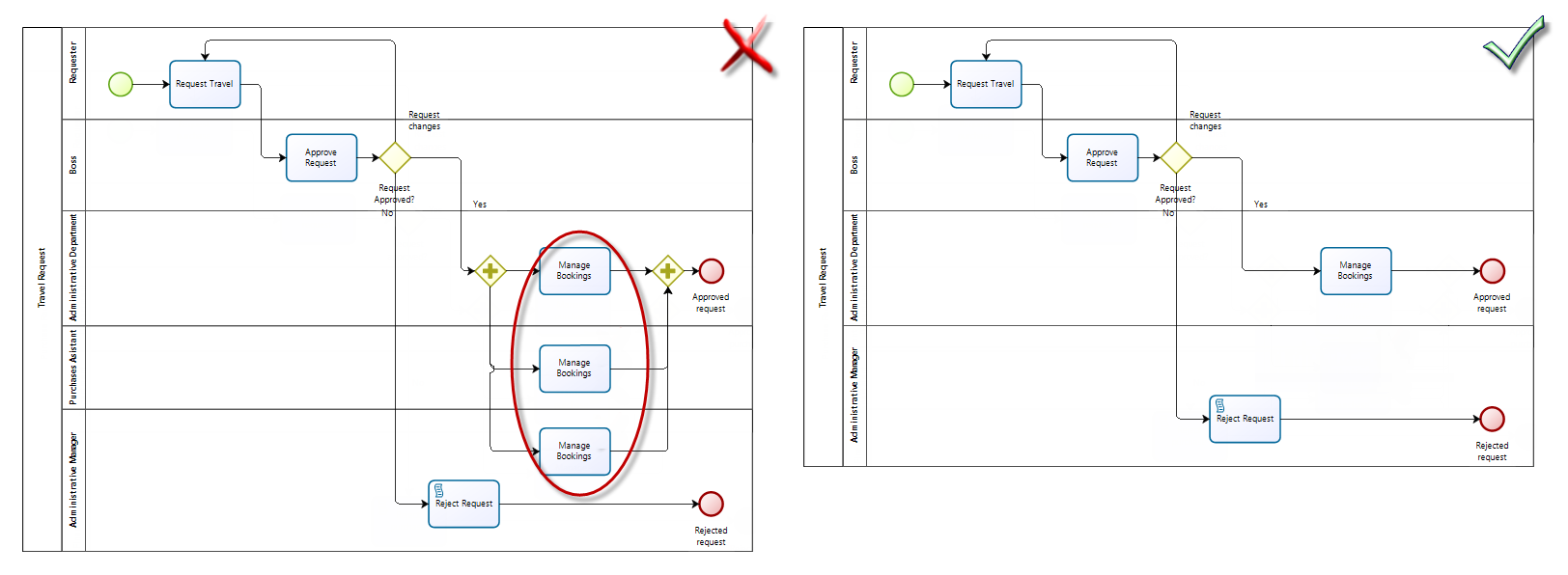
•Do not diagram multiple instances of the same task to represent multiple performers. Just diagram one task in one area. Define the multiple performers as Allocation Conditions in the documentation.

•Do not branch flows using tasks. Always use gateways to do so.

What to check in Gateways
•Do not use gateways to join and split at the same time.

•Balance gateways. Splits must be joined equivalently.

•Always use the same type of Gateway used as for splitting to join the flow.

What to check in Events
•Always use start and end events.

•Use terminate events only when this is strictly necessary. They are used to model situations where several alternative paths are enabled and the entire process have to be finished when one of them is completed.

What to check in Connectors
•Use sequence flows to connect all the activities, events and gateways. Never use message flow to connect activities within the same pool or leave shapes unconnected.

•Never use sequence flows to connect elements of different pools. Use message flows to represent information exchanging between processes.

What to check in Milestones
•Always identify and define phases; these represents a period of time goal or transition in the process.

•Avoid come back or looping back across a milestone.

3. Use strict labeling
Correct labeling of the different elements of the diagrams is fundamental for an easy and correct understanding of processes. Here are some recommendations to help you do so:
Labeling Processes
Processes labels should clearly describe their main purpose. Make sure that you do not use short names or abbreviations.
Labeling Activities
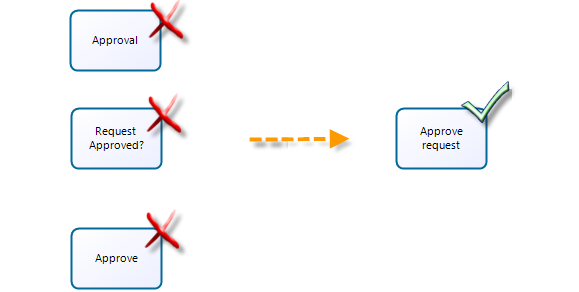
Give activities a label composed of one verb, and one object. This way readers can clearly understand the objective of a task. Also, make sure that you do not use short names or abbreviations.

Labeling Events
Do not label start and end events when only one instance of them is used. It is very common to label them as "Process start" and "Process end" but this is redundant and not necessary.

•Use labeling when multiple start and end events are used. Label them according to what they represent using a noun. Do not repeat names.

Labeling Milestones
Milestones should be labeled with a noun making reference to a period of time (summer, maturity) or what happens in a period of time (creation,approval, delivery).

Labeling Gateways
Divergence gateways should have a clear name indicating the decision or condition evaluated when it applies. Use a name composed of one verb, one object, and a question mark to identify what is being evaluated. You can even use questions to clarify the decision involved.

•If names do not apply for any gateway use abbreviations or numbers to differentiate them.

•Name transitions indicating the condition related

4. Simplify diagrams
Large diagrams do not allow giving an end-to-end perspective to readers. They are difficult to read and clearly communicate the purpose of the process.
Defining the correct scope of tasks and level of detail of processes is key to reduce the overage of information. The following tips will help:
Reduce the number of redundant tasks
The level of detail in a process is sometimes a true challenge. In many cases you may face difficulties to define the scope of a single task. Take into account that:
•When diagramming it is useful to imagine that you are a final user. If a set of consecutive activities can be performed by the same person, at the same time then these activities could be integrated into a single activity.
•A set of consecutive activities in the same lane may indicate missing participant details, too much detail, or a misalignment in scope. Review these patterns to identify opportunities for activity integration.

Group activities
Use sub-processes to group activities with the same purpose. You can expand the sub-processes later to expose details of lower levels of hierarchy. A process will contain multiple pages, but internally the integrity of a single model is maintained.
Use embedded sub-processes when:
•A set of consecutive activities has an owner different from the main process owner (e.g a Purchase request process is performed by the Purchasing area and the Accounts payable process is performed by the Financial area).
•A set of consecutive activities has an different goal from the main process one (e.g a Credit request is focused on managing all the activities to approve a credit request and the Verify applicant information is focused on checking if the applicant is in the black list as well as the information submitted).
Use reusable sub-processes when:
•The sub-process needs to be invoked from different processes (e.g a Verify applicant information sub-process can be invoked from a credit request process or from a Insurance request process).
Apply process patterns
Do not reinvent the wheel. BPMN experts have worked on defining modeling patterns to different business situations. Use them to model the required business conditions while simplifying your diagrams.
Document minor details
Leave details to documentation. Do not include all the information on diagrams. Additional information should be documented as shape properties not as objects or text in the diagram.
Last Updated 2/4/2026 9:51:29 AM